Security of the Intel Graphics Stack - Part 1 - Introduction
I promised I’ll post stuff about low level hardware issues, and here is my second post on the subject, the first part in a series about the Intel graphics stack.
This post series will be a summary of about a decade of unpublished research I am trying to organize and share. Not all of it is current, as newer hardware is harder to inspect and reverse, but I think much of the research is relevant.
The first post below is a quick introduction to the different components on the hardware and software side we’ll need to dive into security issues in the next post.
General Architecture
- Processor graphics - The graphics unit that is part of the processor itself. Has had many codenames over the years, HD Graphics, UHD Graphics, Iris, Gen9, Gen11, Intel Xe and so on. Even the ‘Gen’ name has double meaning - both generation and ‘Graphics ENgine’. In UEFI code it is sometimes refered to at the IGD - Integrated Graphics Device.
-
The GuC - an embedded i486 core that supports graphics scheduling, power management and firmware attestation.
- UEFI and OS Drivers
Core Graphics
As discussed in the introduction to the SecureBoot post, the Intel CPU has four major component groups - the CPU cores, the L3 (or LLC) cache slices, the ‘Uncore’ or ‘System Agent’ parts, all connected through a ring bus inside the die.
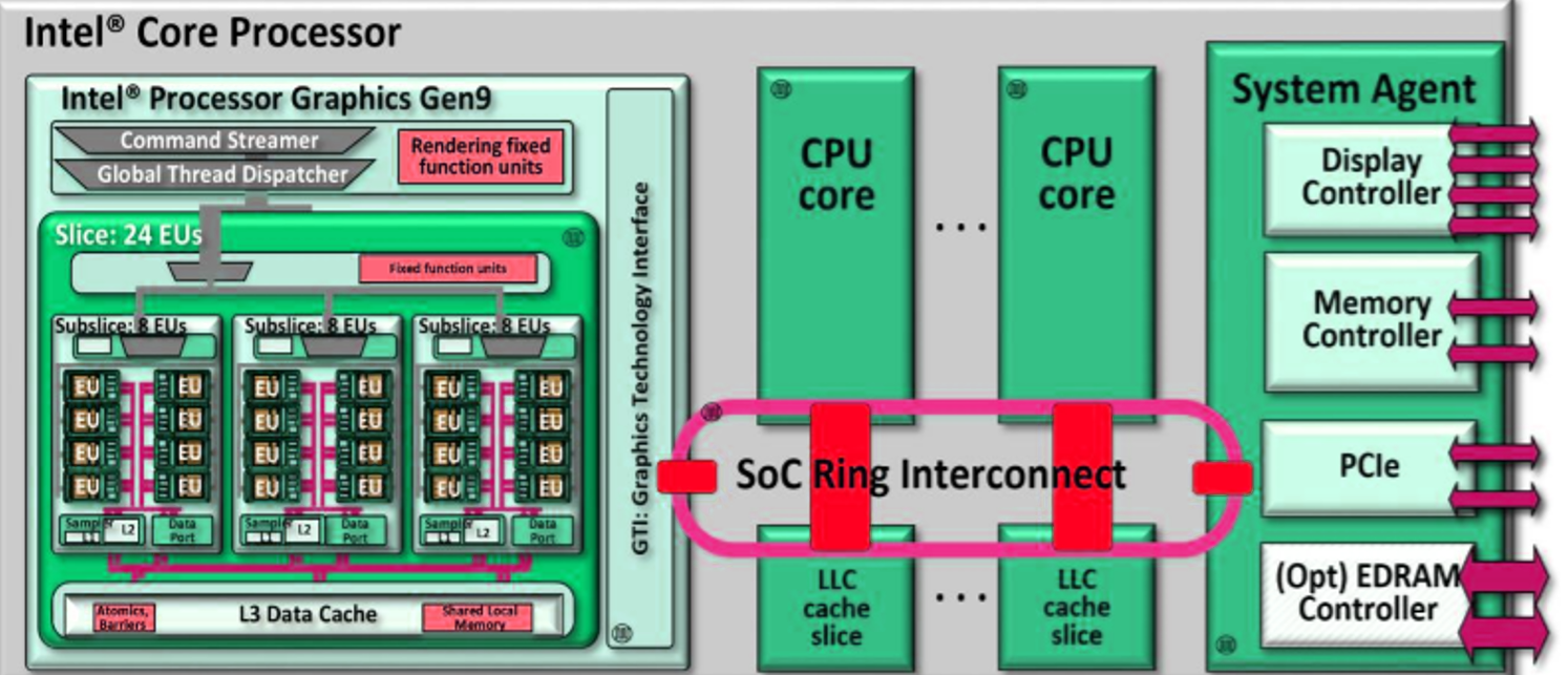
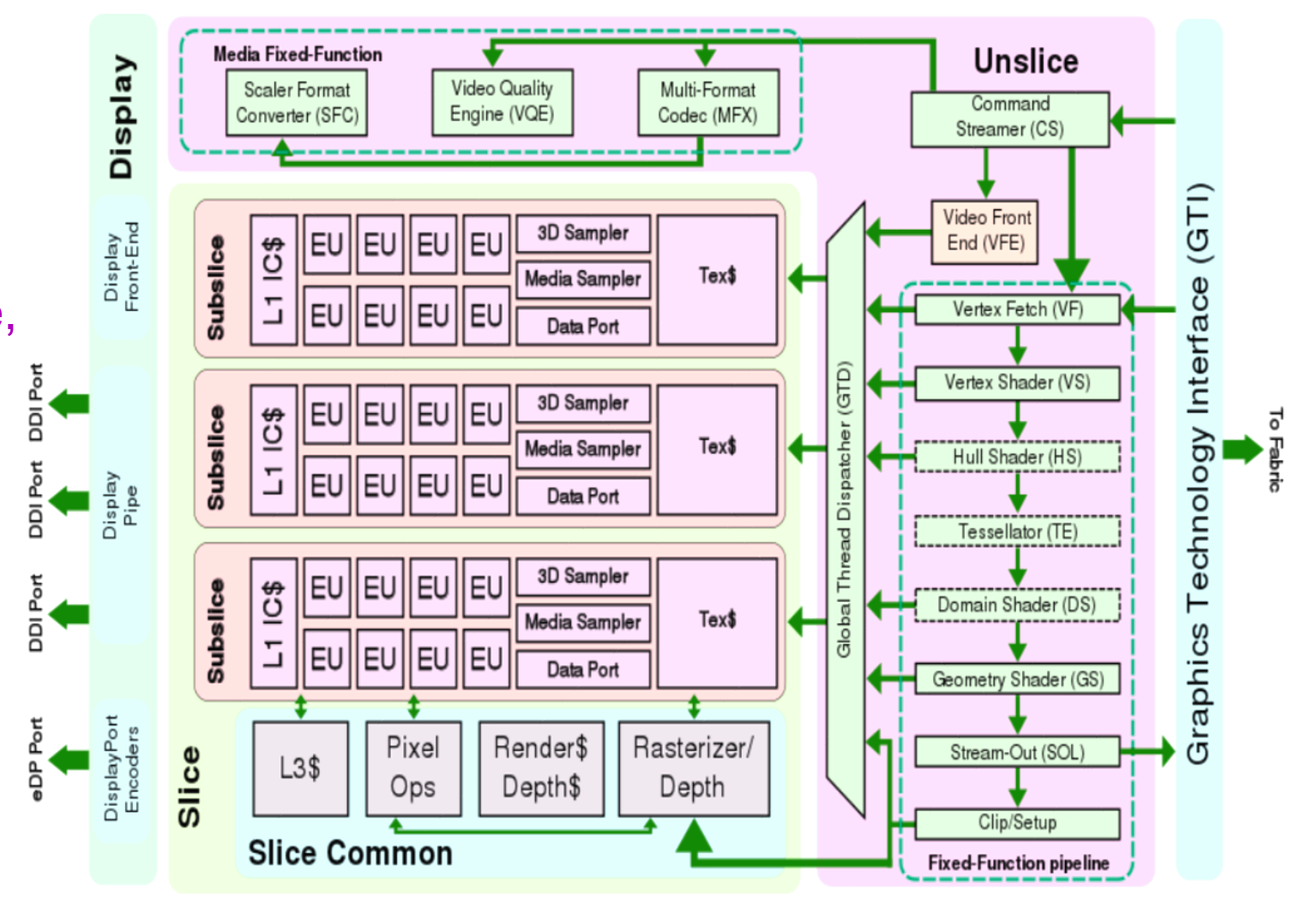
The graphics process is made up from several slices and an unslice (like uncore) area that includes common components. Each slice is divided into subslices and a slice common area. The subslices are made up of several Execution Units (EUs), and Texture unit and a L1 Cache/Memory. The common area includes the L3 cache and the dataport. The limit to the number of slices is the interconnect between them and the unslice. There is always only a single unslice. In the unslice we can find the connection to the ring bus, aptly named the GT interface (GTI), the Command Streamer is reads commands from the system memory and into the graphics processor, the fixed function pipline (FF pipeline), and the thread dispatcher \& spawner that lunch shader programs and GPGPU (General Purpose Computing) programs onto the EUs. The FF pipeline deals with fixed functions such as vertice operations (called the Geometry Pipe), and other dedicated hardware such as video transcoding.
Different SKUs have different combinations of these. For example:
- Skylake GT2: 1 slice of 3 subslices of 8 EUs (1x3x8)
- Skylake GT3: 2x3x8
- Skylake GT4: 3x3x8
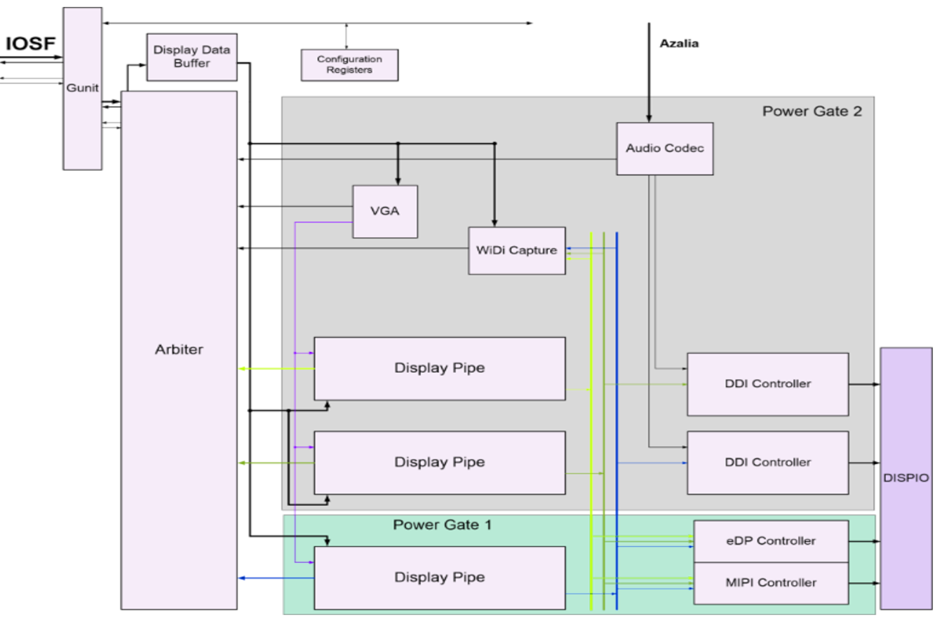
The graphics engine is also connect straight to the IOSF (Intel On Chip Fabric internal bus, see the secureboot post bus, through a controller called Gunit. Gunit is connect to both the primary and secondary IOSF and exports functions for communicating with the graphics engine and implementing IOMMU support for graphics memory and unified memory.
All of this is connected to the display IO interconnect and output to DisplayPort and HDMI outputs.
2D Graphics Pipeline
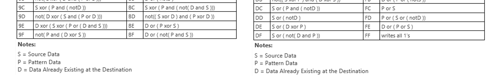
The 2D graphics engine is a standalone IP block in the unslice area, and has its own command streamer, registers and cache. It has 256 different operation codes, for example:
3D Graphics Pipeline
The fixed function pipeline in the unslice implements the DirectX 11 redndering pipeline stages: Vertex Fetch -> Vertex Shader -> Hull Shader -> Tessellator -> Domain Shader -> Geometry Shader -> Clipper -> Windower -> Z Ordering, -> Pixel Shader - >Pixel Output. Some of these functions are self contained, but many are implemented using by running shader programs on the EUs in the slices. EUs can send certain operations back into dedicated hardware units.
The Execution Units (EUs)
The EUs are in-order mulithreaded SIMD processing cores. Each execution thread is dispatched has its own 128 register space and executed programs called “kernels”. All instructions are 8 channels wide, e.g. operate on 8 registers at a time (or 16 half registers). Its supports arithmetic, logical and control flow instructions on floats and ints. Registers are addressed by address. The EU thread dispatcher implements priorities based on age, i.e. oldest is highest priority, and whether the trhead is blocked waiting on instruction fetches, register dependencies etc’. C
The GuC
The GuC is a small embedded core that supports graphics scheduling, power management and firmware attestation. It is implemented in an i486DX4 CPU (also called P24C and Minute IA), although it seems that since broadwell it has been extended to the Pentium (i586) ISA. It runs a small microkernel call μOS. The GuC μOS runs only kernel level tasks (even though μOS supports μApps). The firmware is written in C with not stdlib. In the GuC we can find supporting blocks: ROM memory, 8KB L1 on core cache, 64KB/128KB/256KB (Broadwell/Skylake/CannonLake) of SRAM memory which is used for code+data+cache and a 8KB stack. It also has power management, DMA engine, etc’. Communication to the GuC is done through memory-mapped IO and bidirectional interrupts.
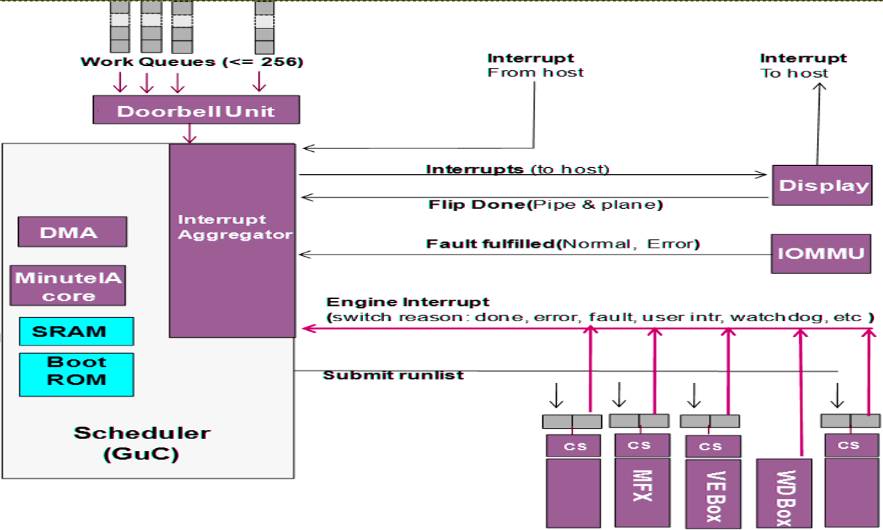
The GuC offers a light-weight mechanism for dispatch work the host submits to the GPU. This means the GPU driver does not need to handle dispatch and job queuing, making it much faster. The user mode driver (UMD) can communicate with the GuC directly when required and bypass the need to context switch the main CPU into kernel mode. The kernel mode driver (KMD) uses the GuC as a gateway for job submission as well. This simplifies the Kernel and provides a single point where all jobs are submitted. Communication between the UMD and the GuC is done through shared memory queues.
Why is the GuC interesting? Because I think it can communicate with the CSME, CPU and GPU and everything over the IOSF, and if it has bugs it can be used to gain very privileged access to the system and memory.
Boot ROM and GuC firmware
At system startup GuC is held at reset state until the UEFI firmware initializes the shared memory region for the GPU. Inside the shared region a special subregion call WOPCM is set aside fur GuC (and HuC) firmware. It then releases the GuC from reset and it in turn starts executing a small non-modifiable Boot ROM (16/32KB in size) that initializes the basic GuC hardware, and waits for an interrupt signalling the firmware has been copied to the WOPCM region. The GuC firmware is an opaque blob supplied by Intel as part of the GPU KMD, which copies it to the shared memory region (GGTT) and signals the Boot ROM with an interrupt. The bootrom verifies the firmware with a digital signature using a SHA256 hash + PKCSv2.1 RSA signature, and if the test passes copies it to SRAM and starts executing.
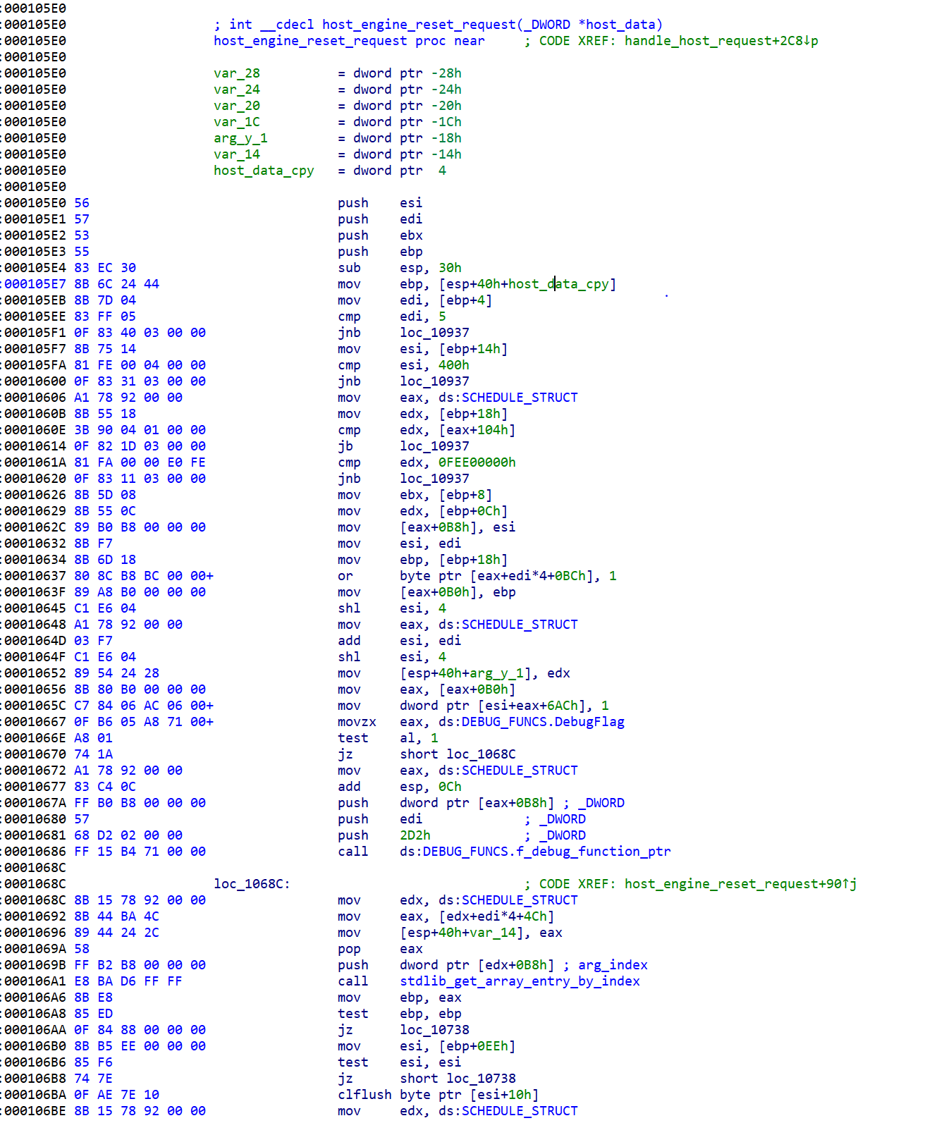
The GUC firmware can be extracted from the graphics driver and reversed. Screenshot of IDA open on the kabylake GuC:
The GuC also attest the firmware for the video decoder unit, called HuC. The HuC is an HEVC/H.265 decoded implement in hardware.
The μOS kernel
The μOS kernel runs in 32-bit protected mode, with no paging and old-style segments model (CS, DS, etc’). All code run in ring0. The OS handles HW/SW exceptions and crashes, and supplies debugging and logging services.
Interrupts are handled through the local APIC - I found interrupts coming from the IOMMU, power management, display interfaces, the GPU and the CPU.
It runs a single process - which initializes the system and then waits for interrupts/events in a loop.
Communication with the OS
Commands are dispatched through a ring buffer work queue. Each work item has a header followed by a command. Once a command is posted the CPU notifies the GuC using a “doorbell” interrupt.
The Windows kernel mode driver supports GuC debugging by setting a registry key:
\\REGISTRY\MACHINE\SOFTWARE\Intel\KMD\GuC\\
	GuCEnableUkLogging=1

\\REGISTRY\MACHINE\SOFTWARE\Intel\KMD\GuC\\
    GuCLoggingVerbositySelect=0/1/2/3 (low, medium, high, max)
Host Graphics Architecture
So far we only discussed hardware. The software part of the graphics stack is divided into three levels: UEFI DXE, kernel mode and user mode.
UEFI
Traditionally VGA support was implemented with a legacy Video VBIOS as an PCI option ROM. In UEFI VBIOS was modified into a DXE driver call the Graphics Output Protocol (GOP), which support basic display for the UEFI setup menu and for the OS bootloader. The GOP is supplied by Intel to the UEFI vendor. The GOP supplies two basic functions:
- Changing the graphics mode - resolution, pixel depth, etc’
- Getting the physical address of the framebuffer
The Windows boot-loader uses the GOP to setup a memory mapped video framebuffer before entering VBS, and after the hypervisor and SK are loaded the access by winload is only through the framebuffer without invoking the GOP. Windows also uses the GOP for disabling blue screens.
Windows
On Windows, Intel supplies a fairly large graphics driver that implements both the user mode driver (UMD) and kernel mode driver (UMD). Applications using Direct3D communicate through the D3D runtime to the DXGI abstraction interface (in dxgkrnl.sys), which in turn communicated with the KMD. The KMD treats 2D Blt and 3D operations through different pipelines and dispatches the operations to the GPU.
The GPU driver is riddled with telemetry, but I haven’t figured out yet how much of it is sent automatically to Intel, altough crashes are sent through OCA - Online Crash Analysis.
Basic Memory Management
A very important job of the graphics drivers (both KMD and UMD) is memory management (GMM). The Graphics Memory space is the virtual memory allocated to the GPU, and is translated using the system pages tables to the physical RAM. The memory contains stuff lime geometry data, textures, etc’. The GPU hardware used Graphics Page Tables (GTTs) to decode virtual addresses supplied by the software graphics memory space into hardware. The use of MMUs and page tables on both ends (sw \& hw) has three main benefits: virtualization, per-process isolated graphics memory and non-contiguous physical memory for better utilization.
The GTTs come in two variants:
-
Global GTT - a single one level table mapping directly into system pages. It is managed by the HW and configured in UEFI. The UEFI DXE driver maps the GTT into memory and initializes it. It is also called Graphics Stolen Memory (GSM) and Unified Memory Architecture (UMA), not to be confused with CSME’s UMA.
-
Per-process GTT (PPGTT). This has changed significantly in the Broadwell graphics engine, so we’ll discuss only the new architecture. Modern PPGTT is basically a mirror of the CPU’s paging model with 4 paging levels.
The GMM part of the KMD handles and tracks graphics allocations, manages the GTTs, caching coherence, stolen memory allocation and something I won’t go into right now called swizzling. The GMM is essential for performance as it allows memory to be setup by the CPU and then accessed by the GPU directly without copying from system memory to GPU memory.
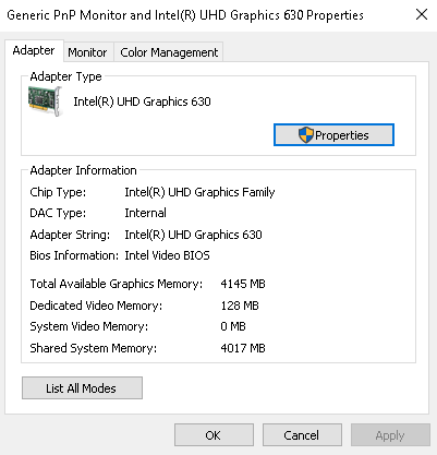
Its important to note that in modern system the whole system memory can be used for graphics. The driver reports fictious “dedicated” video memory probably to fix old games.
Security-wise, the graphis driver needs to make sure user process can gain access only to memory allocated to that process, and is cleared before transferring the memory to a different process.
SVM Mode
The Intel GPU have added support for another organic memory model, the OpenCL SVM model. In SVM mode the GPU and CPU share the exact same page table, so data structures can be shared AS-IS between both, including embedded pointers and such. Five levels of SVM are supported.
- Coarse grained - CPU \& GPU have different buffers
- Fine grained - CPU \& GPU can share memory buffer
- Fine grained system - CPU \& GPU share entire system memory
+-----------------+------------------------------------------------------------------------------+
|                 | Type                                                                         |
+-----------------+-----------------------+--------------------------------+---------------------+
|                 |  Coarse-graind-buffer | Fine-grained buffer            | Fine-grained system |
+-----------------+                       +-----------------+--------------+                     |
| Type            |                       | without atomics | with atomics |                     |
+-----------------+-----------------------+-----------------+--------------+---------------------+
| Shared          | V                     | V               |        V     | V                   |
| virtual         |                       |                 |              |                     |
| address         |                       |                 |              |                     |
| space           |                       |                 |              |                     |
+-----------------+-----------------------+-----------------+--------------+---------------------+
| No need for     |                       | V               |        V     | V                   |
| explicit        |                       |                 |              |                     |
| mapping by host |                       |                 |              |                     |
+-----------------+-----------------------+-----------------+--------------+---------------------+
| Fine-           |                       | V               |        V     | V                   |
| grained         |                       |                 |              |                     |
| coherency       |                       |                 |              |                     |
+-----------------+-----------------------+-----------------+--------------+---------------------+
| Fine-           |                       |                 |        V     | V                   |
| grained         |                       |                 |              |                     |
| synchorinzation |                       |                 |              |                     |
+-----------------+-----------------------+-----------------+--------------+---------------------+
| Implicit use    |                       |                 |              | V                   |
| of memory       |                       |                 |              |                     |
| from CPU        |                       |                 |              |                     |
| malloc() from   |                       |                 |              |                     |
| GPU and entire  |                       |                 |              |                     |
| CPU address     |                       |                 |              |                     |
| space           |                       |                 |              |                     |
+-----------------+-----------------------+-----------------+--------------+---------------------+
Cache Coherence
Both the CPUs and GPUs have a complex memory hierarchy involving many caches. For example:
CPU: L1 Cache -> L2 Cache -------------\
                                       |------> *System LLC Cache -> eDRAM -> RAM
GPU: Transient Cache -> GPU L3 Cache --/
GPU memory accesses do not pass through the CPU core’s L1+L2 caches, so the GPU implements snooping to maintain memory-cache coherency. The GPU basically sniffs the traffic on the CPU L1/L2 caches, and invalidates its own cache (I think this is relevant only to BigCore CPUs, and on Atom this is optional and very costly). The GPU’s transient caches are not snoopable by the CPU and must be explicitly flushed. The GPU L3 Cache is snoopable by the CPU on some Intel platforms.
Boot process
At boot, the operating system and kernel mode drive will detect and query the display devices, initialize a default display topology. After boot up, display config request will be sent to KMD and KMD in turn will configure the GEN display hardwires There are also use cases of display hot-plug during runtime, handled by OS user and kernel mode modules/drivers.
Once the driver is loaded it DirectX initializes it from DxgkDdiStartDevice() which eventually leads to a function that setups the render table per architecture:
void setup_render_function_table(HW_DEVICE_EXTENSION *pHwDevExt)
{
    KM_RENDER_CONTEXT   *render_context;

    ...

    switch(get_render_core(pHwDevExt))
    {
    ...
        case GEN3_FAMILY:
            ...
        case GEN4_FAMILY:
            ...
            ...
        case GEN8_FAMILY:
            render_context->FuncTable.PresentBlt                     = func_Gen6PresentBlt;
            render_context->FuncTable.PresentFlip                    = func_Gen6PresentFlip;
            render_context->FuncTable.RenderBegin                    = func_Gen6RenderBegin;
            render_context->FuncTable.Render                         = func_Gen7Render;
            render_context->FuncTable.RenderEnd                      = func_Gen6RenderEnd;
            render_context->FuncTable.GDIRender                      = func_Gen6GDIRender;
            render_context->FuncTable.BuildPagingBuffer              = func_Gen7BuildPagingBuffer;
            render_context->FuncTable.SubmitCommand                  = func_Gen8SubmitCommand;
            render_context->FuncTable.PreemptCommand                 = func_Gen6PreemptCommand;
            render_context->FuncTable.QueryCurrentFenceIRQL          = func_Gen6QueryCurrentFenceIRQL;
            render_context->FuncTable.IdleHw                         = func_Gen6IdleHw;
            render_context->FuncTable.StopHw                         = func_Gen6StopHw;
            render_context->FuncTable.ResumeHw                       = func_Gen6ResumeHw;
            render_context->FuncTable.GetMDLToGttSize                = func_GetMdlToUpdateGTTCmdSize;
            render_context->FuncTable.UpdateMDLToGtt                 = func_MDLToGttUpdateGttCmd;
            render_context->FuncTable.GetMDLToGttSizeOnePage         = func_GetMdlToUpdateGTTCmdSizeOnePage;
            render_context->FuncTable.UpdateMDLToGttOnePage          = func_UpdateOneGttEntry;
            ...
OCA
OCA is a mechanism that lets drive store device data and send it through windows update back to the driver vendor. There are two cases of failures:
- Windows thinks there is a problem and the driver needs to be reloaded (TDR). Windows calls
DxgkDdiCollectDbgInfo(), a mechanism that lets drive store device data and send it through windows update back to the driver vendor. The Intel GPU driver can add more then 1MB of data throughDxgkDdiCollectDbgInfo(). - In case of a blue screen (bugcheck), KmBugcheckSecondaryDumpDataCallback() is called and the driver passes data to it.
After both function the data is converted into an OCA blob using
CreateOCAXXXDivision, and it is later uploaded to Microsoft and from there to Intel. The Intel OCA blob contains lots of system and driver information, including what appears to be an Intel specific unique identifier assigned by the driver to the machnine and can be used for tracking.
Conclusion
In this post we learned the basic components of the graphics stack. In the next post on the graphics stack we’ll start looking into security implications.